Aberthaw Tidal Power Station
2019 Outline Design by Edward Grist
(8) Structure and Assembly
Contents
Layout
- the rapid installation of machinery during barrage construction
- the ready transfer of defective components to the Central Workshop for major repairs during the life of the power station and
- an easily achievable 'within two years' end-of-life removal of the barrage down to estuary floor level
Main Frame Units (MFU)
- main columns to be removed and
- root-tubes to be cleaned out for reuse
- Individual items of equipment used in the generation of tidal power are replaceable within two hours following an identified failure
- The loss of generating capability from tidal power following a credible external event that causes major damage is limited by design to a maximum of 20 percent of the barrage rated output and this loss is restorable within 180 days
Root Tubes & Depth Adjustment Boxes (DAB)
MFU Installation
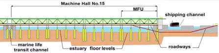
The Aberthaw-Minehead Tidal Power machinery - water turbines, electricity generators and related equipment - are contained within fifteen Machine Halls. Roadway tunnels adjacent to the English and the Welsh shores pass under shipping channels and effectively form an 'Island Barrage'. These tunnels provide roadway access to the Machine Halls.

The 'Island Barrage' as it crosses the estuary.
The contents within each Machine Hall are housed in one of four Main Frame Units (MFU). The Machinery Hall design permits the ready access by cranes to all the equipment used in electrical power generation.
It enables all the tidal power machines to be separately removed and transported to and from the dockside at either of the two shipping channels.
This in turn permits
A barrage based on MFU suspended from columns has considerable advantages. It is structurally very light and is capable of being rapidly replaced. It tolerates estuary bed movements caused by seismic events including earth tremors. At the barrage construction stage the columns are readily put in place to an appropriate location accuracy using the technology employed when installing wind-turbine towers in the North Sea. The MFU are also easy to install using the falling tide and barge pairs adapted for this purpose.
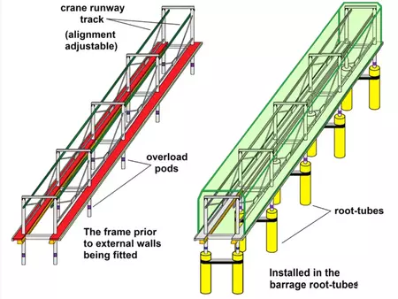
The MFU design - A view of the framework and of the final assembly
Machine Hall (no boxes installed), MFU and 'stepped' estuary floor
The MFU are distributed uniformly across the barrage. The number of water turbines is chosen to match existing estuary flow patterns.
The design recognises that the MFU could during its lifetime be subjected to a very large horizontal force being inflicted high up on the structure - such as during a ship collision. To make the MFU replaceable within 180 days after such an event the design includes features that isolate such force from the foundations. This is achieved by dividing each vertical column into two parts, a main column and a 'root-tube'. The main column sits loosely in the root-tube on initial assembly. Built into each main column is an 'overload-pod' (The purpose of this pod is to be the weakest link and break when a critical bending moment is applied. This avoids irreparable damage to the root tube and column foundations.
This Aberthaw-Minehead Tidal Power design restricts damage to a manageable level that, at the worst, requires
A fundamental requirement and prime objective is to maximise the electrical power generated for the National Grid. Circumstances limiting the ability to generate are inevitably brought about by equipment failure resulting from 'normal' wear and tear. The cause of a failure can also be the result of an extreme event such as a malicious attack. Recognising credible possibilities and minimising the impact on power generation by appropriate design is essential. The Aberthaw – Minehead barrage does this by meeting the following two design requirements without exception.
All MFU are of an identical design that is nominally 220m long. They are upstream/downstream symmetrical making it immaterial which side of the MFU faces upstream at the time of installation.
All T-G boxes (housing turbine-generators, pipework and associated equipment) are of an identical design that is nominally 50m long and 14m deep.
All T-G boxes (housing turbine-generators, pipework and associated equipment) are of an identical design that is nominally 50m long and 14m deep.
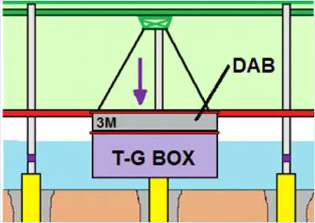
As the barrage crosses the estuary the shallow water off Minehead changes to deep water in the shipping hannels and then back again to shallow water as it reaches Aberthaw. The means of accommodating an increasing estuary depth within a Machine Hall by the use of a root-tube and a DAB (Depth Adjustment Box) of the same additional length. DAB available in length increments of three metre are appropriate. The above only applies within the Machine Halls. The marine life transit channels are excluded from this process. They retain the natural estuary bed level.
The maximum box height that can be transported by a barrage main crane through the adjoining Machine Halls to either the Central Workshop or the shipping channel dockside has been chosen to be 18 metres. This sets the crane rail height. Pairing a standard T-G box and a DAB in a single assembly covers all possible water-turbine runner submergence requirements. Every T-G box is a fixed height of 14m. This permits any T-G box to be used in any Machine Hall location. The benefits of T-G box interchangeability are considerable.

By adding a root-tube of different length
By adding a DAB (Depth Adjustment Box) or the same length change as the root-tube
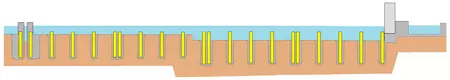
The barrage prior to MFU installation
(Four MFU in the Machine Hall length shown)
Major activity at the barrage site starts by preparing the estuary bed. This includes removal of debris, levelling into 'steps' where necessary, installing the root-tubes and laying the separate National Grid power line connectors to Aberthaw and Minehead. The construction of the transit channels (without bascules and associated machinery) follows. Finally, in preparation for the arrival of structural steelwork in the form of the MFU, a concrete surface for sealing beneath the T-G boxes is put in place.
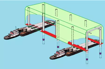
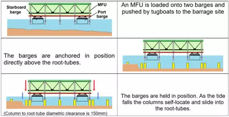
MFU delivered by tug/barges on a falling tide
(The green curtain wall is partly removed to show the loading arrangement)
The estuary is now ready to receive the MFU. Each MFU is manufactured and delivered to an estuary dockside where it is loaded onto two barges. Two 'tugs' then push the barges to the barrage site. As illustrated they hover over their allocated root-tubes and are allowed to locate and settle into them as the tide falls. The MFU stops its downward movement when its columns reach their final locating surface in the root-tube. As the tide continues to fall the barges sink lower relative to the MFU until they finally become free. The tugs then remove the barges. The diametric clearance is then filled. This completes the installation.